
![]()


 |
| 
Article Index
HIGH VOLTAGE - CAEN
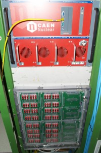
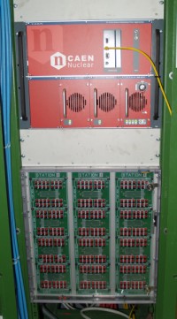
The bias voltage in the Silicon Tracker detector is based on a standard (non radiation resistant) CAEN solution. These systems are widely used in high energy physics and have proven to be very reliable. Hard- and software for the integration in the LHCb ECS system will be available.
The layout for IT subdetector can be seen below. We plan to supply the 336 ladders of IT with one SY1527 high voltage crate with 8 A1511B modules. Each module provides 12 floating channels up to 500V and 10mA each. Studies on radiation damage for IT ladders shows that after 10 years of LHCb their bias current consumption will be below 2mA per ladder. In order to reduce costs, four detector ladders will be connected to one supply channel. This will be done on a special HV patch panel in the counting room. This connection of several ladders to one supply channel generates grounding loops, which are however separated by the high impedance line filtering on the hybrids (see Figure 1) and should thus not impose any problem.
The grouping of four ladders into one bias voltage channel is done according to the same granularity as the eight fold data readout granularity, which was optimised according to the expected occupancy. One readout section corresponds therefore to two bias voltage supply sections.
After the HV patch panel in the counting house 12 multi-wire cable will pass through the wall, one per IT box. In the cavern, a second HV patch panel will split this 56-wires (28 channels) cable into 4 14-wires (7 channels) cables, one per layer.
For the TT subdetector, the case is different as the radiation and thus the expected bias currents are higher. Here we plan to supply the central ladders individually since the radiation damage they suffer is quite high, and the external ones will share the HV channel as in the IT. Therefore a special HV patch panel located in the couting room will be also built for the TT. One SY1527 crate with 13 A1511B modules will be used. 6 cables of 24-wires will feed each detector quadrant. A pseudo HV patch panel (connector to connector) is foreseen in the cavern to separate the moveable part of cable (20m) from the fixed one (80 m).
In both IT and TT the shield of cables will be connected to the main ground of the experiment. In order to allow a possible HV upgrade all modules are wired up to the counting house.