Article Index
LOW VOLTAGE-MARATON
The power supply system is kept completely floating, only in the detector box the main grounding point will be connected to the general LHCb ground.
Both for the digital and analog power of the hybrid 2.5 V are needed. Two separate radiation hard regulators, type L4913 are located on the backplane of the service box and will provide the voltages. Sense lines for both the voltage and ground lines are used.
Analog and digital ground are connected together on the backplane of the service box, but they are kept floating and not connected to safety ground at this point. Although both grounds are in principle kept separate on the cable as well as on the hybrid layout, they are again connected together on the hybrid at one point to avoid problems due to different voltage drops on the two ground lines.


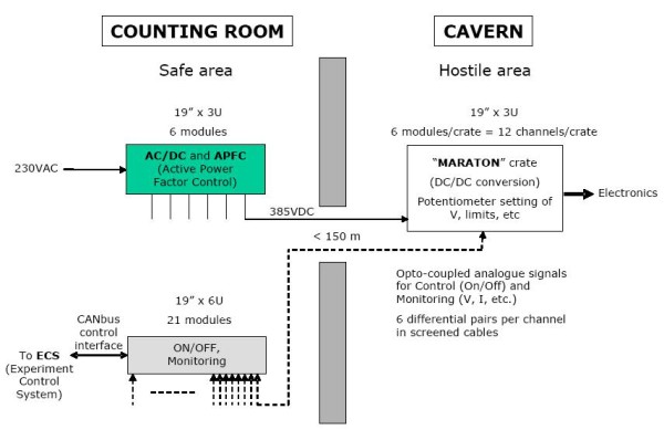
The regulators are supplied by a MARATON system (Magnet field- and Radiation Tolerant New Power Supply System), which is a low noise and low ripple modular power supply system developed for being located in hostile (radiation and magnetic field) environments.
As shown in the figure it consists of three separate parts:
-
Power modules, located in the cavern, which are supplied by a high DC voltage, which they convert into the nominal voltages needed by the service boxes.
-
The AD/DC + APFC board, located in the counting house, which provide the DC supply for the power modules and the Active Power Factor Correction (for EMC issue).
-
The Control + auxiliary power supply board, located in the counting house, also used for monitoring.

AC/DC+APFC and control boards are not tolerant to radiation and magnetic field, so they are located in the safe area of the counting house. For this reason, the settings of the modules output Voltage, Current Limit and the maximum module voltage is done by manually trimming of a potentiomer in the power modules. Limited remote control will be available for ON/OFF channel switching and for monitoring some relevant status signals. A 72-line shielded cable is needed between each MARATON crate (containing 6 power modules) and each control board for 36 differential signals.
Power modules are located in hostile area, and have two floating channels each, with a channel to channel resistance greater than 10 kOhm, and a possible maximum channel to channel voltage of 100 V. These power modules are water cooled (air cooling is not possible since fans do not work properly in magnetic field environments) and all their inductive elements are completely shielded. Available modules that can be used and are of our interest are: 2-7V @ 40A (2x250W) and 5-15V @ 20A (2x300W).
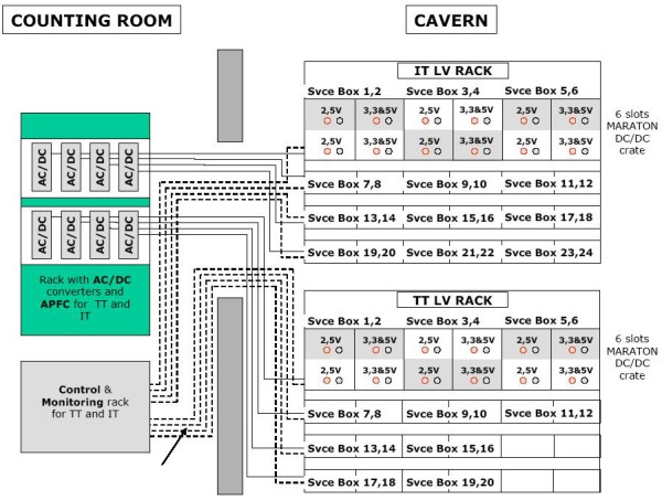
According to the IT and TT power requirements[1][2] and following the MARATON architecture, the layout shown in the figure will be used.

For the IT the requirements are, on one hand, 12 double channel modules of 2-7V, which will supply the 2.5V electronics (hybrids and service box components). On the other hand, 12 double channel 5-15V modules will supply the 5V and 3.3V electronics in the service box. At the output of the 2-7V modules we would need about 5.5V, since we are supposing a dropout voltage of 2.5V in the regulators and a back and forth drop voltage about 0.5V in the cables (length about 20 m) that goes from the MARATON power crates to the service boxes. Using the same reasoning, at the output of the 5-15V modules we would need about 8V. The number of MARATON crates needed for the IT is 4, which implies that 4 AC/DC + APFC boards and 4 Control and Monitoring boards are also needed.
For the TT the requirements are quite similar. The number of power modules needed for each type is 10, and the output voltage of the power modules should be set to a higher value (near 1V), since the drop voltage in the cables will be higher due to the greater current consumption of TT service boxes.


